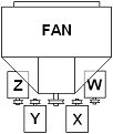
Positions W & Z are the most compact if motor will
fit close to fan. With the current trend to fans on unitary bases (Arrgt. 9H), this
is more common than ever. Positions X & Y will typically take more space.
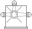
The first sketch on the left shows the motor close to
the fan shaft but it may be more practical to move it out so that a standard adjustable
motor slide base will give a greater adjustment range for belt tension. Longer belt
centers also result in higher horse power.
Arrangement 9 Motor Base Positions
A/9R - Arrangement 9 with motor on right side of
the bearing pedestal.
A/9L - Arrangement 9 with motor on left side of
the bearing pedestal.
A/9T - Arrangement 9 with motor on top of the fan
housing.
A/9SL - Arrangement 9 with motor on left side of fan housing.
A/9SR - Arrangement 9 with motor on right side of fan housing.
Note: RIGHT and LEFT are viewed from the drive side.
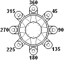
Axial and Inline Centrifugal
A/1L - Arrangement 1 with motor on left. A/1R - Arrangement 1 with motor on right.
Although appropriate for Axial Fans, designations are
AMCA standard 99-2410-82 for Inline Centrifugal
Fans. Alternate designations are o'clock positions.